カテゴリー
category_usa

Cold Cathode Tube

What Is a CCFL Lamp

A CCFL Lamp is a fluorescent lamp, shortened for Cold Cathode Fluorescent Lamp.

While ordinary fluorescent lamps heat their filaments to emit thermal electrons, cold cathode tubes emit electrons without heating their electrodes. Therefore, cold cathode tubes operate at lower temperatures and have a longer life.

In addition, since there is no need to build a filament into the tube, the tube can be made thinner. Fluorescent lamp tubes range in diameter from 15 to 38 mm, while cold cathode tubes are 3 to 5 mm in diameter.

CCFL Lamps cannot be used with standard 50 or 60 Hz commercial AC and require a dedicated power supply that provides high-frequency power.

Applications of CCFL Lamps

CCFL Lamps have more than 30 years of history and have long been used for LCD backlighting, advertising signboards, guide lights, and lighting because of their easy dimming, energy savings, and long life.

In recent years, there has been a shift from CCFL Lamps to LEDs due to the superiority of LEDs over the advantages of cold cathode tubes. LEDs have already completely replaced LCD backlights, and an increasing number of manufacturers are discontinuing the production of cold cathode tubes.

However, CCFL Lamps have advantages not found in LEDs, such as the ability to diffuse light over a wide area and output even, even light, and the ability to produce eye-friendly white light that is close to natural light.

Principle of CCFL Lamp

A CCFL Lamp consists of a long, thin glass tube filled with argon gas and mercury vapor, phosphor coated on the inner wall of the glass tube, and electrodes placed at both ends of the glass tube.

The basic principle of operation of a CCFL Lamp is the same as that of a general fluorescent lamp: electrons emitted from the electrodes combine with mercury ions filled in the glass tube to emit ultraviolet radiation, which excites the phosphor on the inner wall of the tube to emit visible light.

The only difference is the method of electron emission. While ordinary fluorescent lamps emit thermal electrons by passing an electric current through a filament coated with electron-emitting material, CCFL Lamps emit secondary electrons by ion bombardment of argon.

When a high voltage is applied to the metal electrodes of a CCFL Lamp, electrons in the tube are pulled by the positive electrode and move within the electric field, colliding with argon. The argon cations ionized by this collision collide with the negative electrode, emitting secondary electrons.

Since a high voltage must be applied to the CCFL Lamp to emit secondary electrons, an inverter circuit is used as the power supply.

カテゴリー
category_usa

Color Sensor

What Is a Color Sensor?

A color sensor is a specialized device designed to accurately distinguish the colors of objects.

It operates by detecting the wavelength and color of light reflected from or transmitted through objects, converting this optical information into electrical signals. Typically, color sensors are used to analyze reflected or transmitted light from a light source, providing precise color or light-related data.

Color sensors are renowned for their ability to deliver highly accurate color measurements. They excel at detecting even subtle color changes or anomalies, making them invaluable for quality control and optimizing manufacturing processes. Furthermore, their real-time color processing capabilities make them well-suited for high-speed production lines and various application systems.

An important advantage of color sensors is their non-contact operation. In industrial manufacturing, this feature minimizes the impact on product quality.

However, it’s essential to note that ambient lighting conditions can significantly affect color sensor performance. Variations in lighting type and intensity can lead to fluctuations in measurement results, underscoring the importance of maintaining appropriate lighting conditions.

Uses of Color Sensors

Color sensors find applications in diverse fields where precise color detection is essential. Here are some notable examples of how color sensors are utilized:

1. Manufacturing Industry

In the manufacturing industry, color sensors play a pivotal role in quality control. For products with painted surfaces, color sensors assess the color of the paint to ensure it matches the specified color. This consistency is crucial for delivering high-quality products that meet customer expectations.

Color sensors are also frequently employed in the production of molded plastic items to verify color consistency. Additionally, they are integral in the display manufacturing sector, where they analyze ambient light to correct display colors and enhance image quality on devices such as smartphones and tablets.

2. Medical Applications

In the medical field, color sensors serve multiple purposes. They are used to measure skin color and blood oxygenation levels. Changes in skin color can be indicative of circulatory disorders or skin conditions, making color sensors valuable diagnostic tools.

Furthermore, in dentistry, color sensors are used to measure and match tooth color. This is particularly useful for aesthetic treatments and ensuring proper color matching for dental prosthetics.

3. Printing Industry

The printing industry relies heavily on color sensors for quality control. These sensors are essential for maintaining color consistency in printed materials.

Color sensors integrated into printing presses continuously monitor the color of printed materials and make real-time color adjustments as needed. This process enhances color reproduction and ensures consistency across different print jobs.

Principle of Color Sensors

The core principle behind color sensors involves illuminating objects with red, blue, and green light and detecting which wavelengths of light are absorbed and to what extent. When red, blue, and green light are directed at a red object, such as an apple, only the red light is reflected, while the blue and green light is absorbed.

Consequently, only the reflected red light reaches our eyes, causing the apple to appear red. Conversely, when all three colors of light strike a white object, all wavelengths are reflected, resulting in the object appearing white.

The internal structure of a color sensor can be broadly divided into three components: the light emitter, the light receiver, and the processing circuit. The light emitter emits light onto the object under examination to gauge the intensity of reflected light.

The ratio of red, blue, and green light detected by the light receiver is employed to determine the color. The light-receiving component converts this ratio into an electrical signal, which is then processed by the circuitry for color identification.

How to Select a Color Sensor

When choosing a color sensor, it’s essential to consider various factors to ensure it suits the intended application. Key considerations include:

1. Detection Distance

The detection distance of a color sensor represents the maximum range at which the sensor can accurately detect colors. Selection should align with the specific requirements of the application, with longer detection distances being necessary for covering larger areas.

2. Output Type

Color sensors offer different output types, including analog and digital signals. Analog output provides continuous measurement data, while digital output switches signal when a predefined threshold is reached. Additionally, some color sensors offer serial communication outputs. The choice depends on the application’s needs.

3. Connection Method

Consider the connection method between the color sensor and the control device. Common connection options include connectors, terminals, and others. Opt for a method that seamlessly integrates with the control device.

4. Protective Structure

For environments with specific requirements, the protective structure of a color sensor is crucial. Factors like dustproof and waterproof capabilities are often indicated by IP codes, which consist of two numbers, with the first denoting dustproofness and the second indicating waterproofness.
カテゴリー
category_usa

EDA Tools

What Is an EDA Tool?

EDA Tools

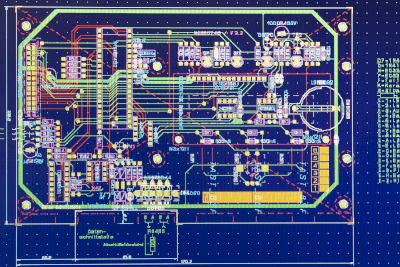
An EDA (Electronic Design Automation) tool is a set of software and hardware tools used to streamline and automate the electrical design process.

It can be thought of as the electrical design counterparts to the CAD and CAM tools commonly used in mechanical design.

For instance, in the design of household appliances, the product design journey typically begins with system (conceptual) design, followed by circuit design, assembly, iterative prototyping, and final product completion. Throughout this process, EDA tools play a crucial role in facilitating product design.

Applications of EDA Tools

EDA tools cater to various stages of the design process. In the context of product design, including household appliances, they encompass tools for system (conceptual) design and simulation, which represents the initial design phase. Additionally, they encompass tools for circuit design and simulation, tools for printed circuit board layout, and tools for mitigating unwanted emissions.

In the semiconductor design field, EDA tools encompass tools for semiconductor device design and their simulation, logic and timing design tools and simulation tools, as well as layout design tools and simulation tools.

Principles of EDA Tools

It is technically possible to proceed with product design without employing EDA tools or by using only a subset of these tools.

However, in today’s competitive landscape, where manufacturers of various products, including household appliances and semiconductor devices, vie on a global scale, the notion of “build it, and it will sell” no longer applies. Success hinges on the ability to swiftly and cost-effectively deliver high-functionality, high-performance products. Consequently, circuits are becoming increasingly compact, smaller in size, lighter, and more power-efficient.

Remaining competitive necessitates an unmatched blend of development prowess and speed in this environment, and EDA tools serve as invaluable aids in achieving this.

The initial step in designing a product entails defining the product’s nature. What functions should it encompass? What should the production cost be? Subsequently, one must devise a system configuration that aligns with this cost target.

System design tools prove to be invaluable in this process. The simulation functionality of system design tools enables the evaluation of whether the virtual system configuration, conceived on a computer, is optimal. This involves assessing whether the performance, functionalities, and costs meet predefined expectations.

If simulation results prove unsatisfactory, the system can be reconfigured, and simulations rerun, iterating the trial-and-error process until an optimal system configuration is attained. Conducting this process by physically building a product would entail significant time and resources, but EDA tools empower users to conduct such verifications swiftly on a computer.

A similar approach can be employed in subsequent design phases, effectively shortening the overall design timeline.

カテゴリー
category_usa

Audio Analyzers

What Is an Audio Analyzer?

An audio analyzer is a sophisticated instrument designed to measure various sound parameters such as distortion rate, frequency response, and signal-to-noise ratio, facilitating the quantitative evaluation of sound quality performance. It integrates the functions of a low-distortion oscillator, filter, and frequency counter into a single device, simplifying the process of assessing sound quality.

With advancements in technology, applications that leverage a personal computer for measuring distortion rates have also become available.

Uses of Audio Analyzers

Audio analyzers are pivotal in assessing the sound quality of audio amplifiers, systems, and other audio-centric devices. They are instrumental in testing speakers and headphones, evaluating audio equipment’s frequency characteristics (like amplifiers and equalizers), measuring stage acoustics, and performing various acoustic tests. They help analyze distortion in audio amplifiers, attributing it to factors such as nonlinearities, residual noise, switching distortion, or harmonic components.

Principle of Audio Analyzers

Audio analyzers feature noise filters tailored to the frequency band characteristics of sound, ensuring accurate sound measurement and analysis. They employ oscillators for precise distortion measurement and analysis, alongside calculation functions for signal analysis. Modern analyzers use digital signal processing (DSP) for signal processing, including noise elimination and harmonic analysis. Additionally, some analyzers can perform intermodulation distortion measurements, employing methods like SMPTE and CCIF to analyze distortion generated by harmonic and difference signals.

Other Information on Audio Analyzers

1. Audio Amplifier Distortion Measurement

Building your audio amplifier involves evaluating the distortion factor, where an audio analyzer proves invaluable. It allows for the input of a low-distortion waveform, measuring harmonics and noise components after filtering out the fundamental waveform, aiming for a low distortion rate as a desirable amplifier characteristic.

2. Distortion Factor Measurement Using a PC

With a Windows PC and USB interface, software like WaveGene (signal generator) and WaveSpectra (measurement software) enable the evaluation of distortion rates. These free software tools are recognized among audio professionals for their ability to analyze audio waveform harmonics and visualize the frequency spectrum of music sources.

カテゴリー
category_usa

Ceramic Substrates

What Is a Ceramic Substrate?

Ceramic Substrates

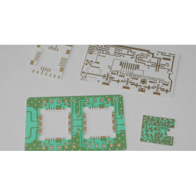
A ceramic substrate is a substrate made of ceramic, which forms the wiring of a printed wiring board or is an insulating board on which components are placed.

Uses of Ceramic Substrates

Ceramic substrates are used in printed wiring boards incorporated in heat dissipation products and high-frequency measuring instruments, etc., as they are used in high-temperature environments and as printed wiring boards become smaller. Specific applications are as follows:

  • Heat Dissipation Products
    High-power LED lighting equipment, laser processing equipment, deep ultraviolet irradiation equipment
    Satellite communication equipment, high-frequency measuring
  • Equipment
    Base station antennas, ETC, RF modules, various radars
  • Automotive Products
    Automotive LED lamps, automotive control components
  • Electronic Components
    Peltier elements, piezoelectric sensors, LEDs, laser diodes, GAN modules, high temperature, acceleration, cycle, SiC power
  • Semiconductors
    High-frequency mobile communication equipment
    IoT communication equipment, antennas and filters, voltage controlled oscillators (VCOs), temperature compensated crystal oscillators (TCXOs)

Characteristics of Ceramic Substrates

Ceramic substrate is made of ceramic and its characteristics are similar to those of ceramics. Typical ceramics that form ceramic substrate include alumina substrate, alumina zirconia substrate, aluminum nitride (AlN), and silicon nitride (Si3N4).

These are materials with excellent mechanical strength, electrical insulation, corrosion resistance, heat resistance, and thermal conductivity, and the substrates have the same characteristics.

Types of Ceramic Substrate

There are three types of printed wiring boards with wiring patterns, etc. formed on insulating substrates made of ceramics: high-temperature ceramic substrate, low-temperature ceramic substrate, and thick film ceramic substrate.

1. High-Temperature Ceramic Substrate

High-temperature ceramic substrate is a substrate on which high-temperature co-fired ceramic (HTCC) circuits are formed. First, an insulating plate, which serves as the substrate, is manufactured using ceramic raw materials formulated for high temperatures. Next, metal circuits such as tungsten and molybdenum are formed on the insulating plate, and the laminated substrate is fired at high temperature to form a High Temperature Ceramic Substrate.

2. Low-Temperature Ceramic Substrate

Low-temperature ceramic substrate is a substrate made of low- temperature co-fired ceramics (LTCC). They are usually manufactured as multilayer substrates.

First, ceramic powder, glass, and binders are mixed to form a sheet. Through holes are made at necessary locations to connect multiple layers, and a wiring pattern is printed and formed to create a single layer. After several layers of different wiring patterns are created and stacked, the LTCC wiring substrate is completed through the firing process.

3. Thick-Film Ceramic Substrate

Thick-film ceramic substrate is a substrate in which electrical circuits are formed by printing conductor or resistor paste on an insulating substrate, and is characterized by the relatively thick film thickness of the conductor.

Other Information on Ceramic Substrate

1 Ceramic Substrate Made of High-Purity Alumina Material

Ceramic substrate is produced by mixing and firing thermally conductive ceramic powder with organic binder and other materials. When high-purity alumina material is used in this process, the fired ceramic has few pores and a very smooth surface because the alumina material is a fine particle.

This means that the material has excellent adhesion to thick films and thin-film materials, and has stable characteristics when used as a printed wiring board. Also, because they are fine particles, their size does not change after firing, and they have very good external characteristics such as dimensional variation, warping, and bending. They also have high heat dissipation and heat resistance, and are physically and chemically stable even under high heat environments. 

2. Semiconductor Packages Using Ceramic Substrate

Heat generation associated with the high integration of semiconductor devices is an important issue, and alumina ceramic substrate with high heat dissipation is used. However, this is not always sufficient to meet the high requirements of today’s semiconductor devices. In recent years, aluminum nitride and silicon carbide have been attracting attention as new ceramic materials for semiconductor packaging that can replace alumina ceramic substrate.

Aluminum nitride is not a natural ceramic material and has excellent thermal conductivity, with a theoretical value of 320 W/m-K. In reality, however, it is difficult to improve the raw materials, burnout, and heat resistance. In reality, improvements in raw materials, selection of sintering aids, and sintering conditions have resulted in the practical application of a thermal conductivity of about 180 W/m-K.

In silicon carbide ceramics, it has become clear that if beryllium oxide is used as a sintering aid, it can be used as an insulator with high thermal conductivity, and it is now attracting attention as a substrate material.

カテゴリー
category_usa

Ceramic Resonators

What Is a Ceramic Resonator?

A ceramic resonator is an electronic component that uses the vibration of a ceramic material, commonly lead zirconate titanate, to create oscillations at a specific frequency. These devices offer a more cost-effective and compact solution compared to quartz-based oscillators, making them suitable for many electronic applications where high precision is not critical.

Uses of Ceramic Resonators

Ceramic resonators are typically used in oscillation circuits for clocks in digital circuits, particularly where miniaturization and weight reduction are prioritized:

  • Digital clocks and smartwatches
  • Timers for home appliances like microwave ovens
  • Automobile engine control units (ECUs)
  • Audio equipment and musical instruments tuning
  • Clock signal generation in data communication equipment
  • Measurement and control devices timing control
  • Robots and automatic control systems
  • Medical device timers and controllers
  • Electronic locks and security systems timing control
  • Battery management in mobile devices

Principle of Ceramic Resonators

The operation of ceramic resonators is based on the piezoelectric effect, where physical deformation and electrical signals are interconverted in ceramic materials:

1. Piezoelectric Effect

Applying an electrical signal to the ceramic material causes it to deform and vibrate, generating a frequency determined by its physical properties.

2. Vibration Control

The resonator stabilizes the vibration through a feedback control mechanism, using the voltage generated from the ceramic’s vibration.

3. Signal Output

The ongoing vibration of the ceramic material produces a voltage, which is then used as a stable clock frequency output.

Characteristics of Ceramic Resonators

Compared to crystal and LC oscillators, ceramic resonators offer several advantages:

1. Compact and Lightweight

Due to the small size of the ceramic materials, the overall circuit can be made compact and light.

2. Cost-Effective

Ceramic materials are relatively inexpensive, making these resonators a cost-effective option for mass production.

3. Low Power Consumption

They generally operate with low power consumption, enhancing energy efficiency in battery-powered devices.

4. High Reliability

Ceramic materials are robust and provide stable oscillations over a wide range of temperatures.

5. Wide Frequency Range

These resonators can operate across various frequencies, suiting a range of applications.

Limitations of Ceramic Resonators

Despite their advantages, ceramic resonators have certain limitations compared to crystal and LC oscillators:

They offer less frequency stability and are not ideal for high-frequency or specific frequency range applications. Unlike LC oscillators, their oscillation frequency is not easily variable, limiting their flexibility in some use cases.

カテゴリー
category_usa

Bus Switches

What Is a Bus Switch?

In electronic circuits, a bus switch is a device that electrically conducts (turns ON) or interrupts (turns OFF) a signal. This is achieved using MOSFETs. The basic role of a bus switch is the same as that of a mechanical switch.

Since it is a switch, it naturally operates in both directions, so there is no need to worry about the direction of the signal.

In the case of a mechanical switch, it only conducts the signal by turning it ON or interrupts it by turning it OFF. On the other hand, some bus switches have a built-in function to amplify the signal or, conversely, to reduce its level.

Uses of Bus Switches

Devices that turn signals on and off in electronic circuits include bus switches and analog switches.

Analog switches are devices designed to perform switching operations in analog circuits. On the other hand, bus switches are devices for digital circuits and are inserted between the CPU and peripheral ICs.

Bus switches are used not only to conduct and disconnect signals but also to switch the connection destination. In the simplest case, for example, if outputs B and C are placed in relation to input A, the bus switch switches from conduction between A and B to conduction between A and C.

Bus switches used in electronic circuits are designed for use in relatively high-speed circuits due to their high-speed switching characteristics.

Principles of a Bus Switch

A typical bus switch is made by combining two MOSFETs: a P-CH MOSFET and an N-CH MOSFET with their gates directly connected and their drains directly connected in parallel.

By inputting a signal from the gate, either the P-CH or N-CH MOSFET will always be in a conducting state, and this is used as the output signal.

A device similar to a bus switch is a bus buffer. A bus buffer has a large fanout number (high drive capability), but there is a delay in switching.

The choice of which device to use should be determined based on the application in the circuit.

Types of Bus Switches

In addition to the aforementioned type that consists of P-CH and N-CH MOSFETs connected in parallel, there are also N-CH type and charge pump type bus switches.

The N-CH type switches ON/OFF by applying a specified voltage to the gate and inputting a signal between the drain and the source.

The charge pump type is made using only N-CH MOSFETs to improve the output signal voltage range.

カテゴリー
category_usa

Power Analyzers

What Is a Power Analyzer?

Power Analyzers

A power analyzer is a device designed to measure the power output of electrical equipment. It enables the assessment of energy conversion efficiency and the identification of malfunctions caused by voltage drops. Although power can be measured with a wattmeter, power analyzers offer the additional capability to measure other parameters such as voltage, current, and frequency, which is not possible with standard power meters. These devices feature multiple channels on the display screen, allowing for the customization of displayed parameters according to the user’s needs.

Uses of Power Analyzers

Power analyzers are instrumental in measuring the efficiency of power generation from renewable energy sources like solar and wind power. Despite the growing popularity of renewable energy for its environmental benefits, it faces challenges such as dependency on weather conditions and generally lower efficiency compared to conventional thermal power generation. Power analyzers help in ensuring the effective supply of electricity and in implementing backup systems when power generation efficiency drops due to energy shortages.

Principle of Power Analyzers

Power analyzers assess the power flow within electrical equipment, employing different calculation methods for DC and AC circuits. In DC circuits, power is calculated by multiplying voltage and current. For AC circuits, however, where current values fluctuate, simple multiplication is insufficient. Power analyzers calculate the RMS (root mean square) value of electrical signals to provide a reliable measure of power current for AC circuits, facilitating accurate power calculations.

Features of Power Analyzers

Modern power analyzers offer:

1. Portability

Designed for field measurements, such as those needed for solar panels, power analyzers are now more compact and lightweight, thanks to advances in technology that condense computing functions into the power analysis engine.

2. Environmental Adaptability

They are engineered for accurate measurements in various temperature conditions, including rapidly changing environments found in constant-temperature rooms and engine rooms.

3. Data Transmission

Wireless technology adapters, such as Bluetooth, enable the transmission of measured data to data loggers or similar devices.

4. Diversity of Interfaces

They support a broad range of standards including USB, LAN, GP-IB, and RS-232C, and offer capabilities for external control and synchronization between units.

Types of Power Analyzers

Various power analyzers available include:

1. Oscilloscope Integrated Type

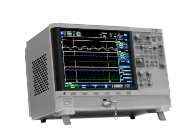
Integrating high-resolution oscilloscopes, these models combine power and waveform measurements in a single device, offering a solution that was not available in earlier power analyzers that lacked waveform observation capabilities. Several manufacturers now offer similar integrated oscilloscope models.

2. High-Precision Measurement Models

These models provide high accuracy in power measurement across a broad frequency range, suitable for detailed analysis of phenomena with large variation ranges and for measuring the switching drive of inverters, with some capable of measuring frequencies above 100 kHz and below 1 Hz.

How to Select Power Analyzers

Power analyzers fall into two main categories based on price: low-priced and high-end models. The selection depends on the required accuracy and frequency range of power measurement. For measurements over 100 kHz, including frequencies of 1 Hz or below, or when high measurement accuracy is essential, a high-end model is recommended. These models are ideal for detailed analysis of wide variation ranges and for measuring inverters and switching drives. For other applications, a mid-range model may suffice.

カテゴリー
category_usa

Voltage Detectors

What Is a Voltage Detector?

A voltage detector is an electronic device used to detect specific voltage levels.

It monitors whether the power supply voltage is within a specified range, ensuring stable operation and proper control.

Uses of Voltage Detectors

Voltage detectors are crucial in monitoring and controlling power supply stability, ensuring system reliability and safety.

1. Reset Circuits for Microprocessors

They monitor supply voltage and generate a reset signal at the proper voltage level, especially during power-on, allowing microcontrollers or microprocessors to initialize successfully and start from a reset state.

2. Control of Power Supply Units

Integrated into power supply units, voltage detectors detect power supply voltage abnormalities and control the circuit to maintain stable power.

3. Battery Management Systems

In battery management systems, voltage detectors monitor battery voltage, detecting overvoltage or undervoltage during charging or discharging, aiding in stable battery operation.

4. System Fail-Safe Functions

They are also employed in system fail-safe functions, safely shutting down systems or activating protective functions upon detecting power failures or unstable voltages.

Principle of Voltage Detectors

Voltage detectors contain a circuit that detects voltage levels at the input terminals. Their typical configuration and operating principle include:

1. Reference Voltage Source

They require a stable, accurate reference voltage for comparison with the input voltage, either produced internally or supplied externally.

2. Comparator

Comparators within voltage detectors compare the input voltage with the reference voltage, outputting the result.

3. Threshold Setting

They set a threshold voltage as the reference. The comparator then determines if the input voltage is above or below this threshold, making a stable threshold voltage crucial.

4. Output Signal

Voltage detectors output a digital signal indicating whether the input voltage is above or below the threshold, which is crucial for monitoring and controlling power supply stability.

Types of Voltage Detectors

Various types of voltage detectors exist, each with specific applications:

1. Fixed-Type Voltage Detector

Fixed threshold voltage detectors are used for power supply monitoring and reset signal generation.

2. Variable-Type Voltage Detector

Variable-type detectors allow users to adjust the threshold voltage, which is suitable for monitoring diverse voltage levels.

3. Dual Voltage Detector

Dual voltage detectors have two independent thresholds for monitoring and controlling different voltage levels.

4. Overvoltage Detector

Specialized for detecting overvoltage, these detectors activate countermeasures when the input voltage exceeds a set threshold.

5. Low-Voltage Detector

Designed for low voltage detection, they trigger countermeasures like current supply limitation when the input voltage falls below a specified threshold.

6. Reset IC

Mainly used in microcontrollers and microprocessor reset circuits, they detect when the power supply stabilizes and outputs a reset signal, initiating normal operation.

カテゴリー
category_usa

Universal Counters

What Is a Universal Counter?

Universal Counters

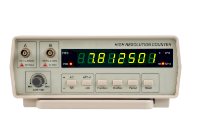
A universal counter is an advanced type of counter for electrical signals, offering additional functionalities beyond the standard period and frequency measurement capabilities of a frequency counter. It can measure pulse width, phase, period relative to pulse width, and the rise and fall times of signals. Additionally, it measures the time difference between two input signals and their frequency ratio, making it a versatile measuring instrument.

Some models can analyze and display data stored over a certain period.

Uses of Universal Counters

Universal counters are instrumental in product development, particularly for circuit design and operational verification of boards based on design results. They are also valuable in technical education settings.

On production and inspection lines, these counters are useful for verifying if the expected frequency and other parameters meet specified values.

While historically expensive due to the need for dedicated logic circuits, recent advancements in low-cost, high-functionality microcomputers and peripheral ICs have made universal counters more affordable.

Principles of Universal Counters

The universal counter measures frequency, a numerical indicator of the number of signals per unit time in a repetitive signal, through the following process:

Initially, input signals are waveform-shaped into clean signals for accurate measurement (signal A). Simultaneously, a gate signal (signal B) specifies the measurement period for signal A. The counter takes the AND of signals A and B and counts the outputs. By counting the number of A signals within a specific period of signal B, the frequency of signal A is determined and displayed on an LCD or through the counter interface.

Most universal counters simplify circuit configuration by using a built-in microcontroller to set the frequency of the gate signal and count the gated signals.