カテゴリー
category_usa

Signal Relay

What Is a Signal Relay?
Signal Relays

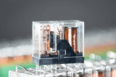
Signal relays are components for electric circuits that turn on and off electrical signals of relatively low current.

Products that open and close signals of about 2A or less are common.

Uses of Signal Relays

Signal relays are used to switch electrical signals on and off. They are used in products that have electric circuits and have a wide range of applications, from home appliances to industrial equipment.

Specific applications are as follows:

Mainly used by mounting on control boards. However, some products are available with an optional dedicated socket for mounting on the DIN rail of the control panel.

Principle of Signal Relays

Signal relays consist of a casing, input/output terminals, insulating parts, and contact switching parts.

1. Casing

The casing protects the signal relay. In most cases, it is made of resinous insulating material. It protects human contact with the electrical circuit. In some cases, simple specifications and serial numbers are printed on the casing. 

2. Input/Output Terminals

These are terminals for sending and receiving signals. Typical input/output terminals are in the form of pins, with multiple pins protruding from the signal relay. Terminals are inserted into special sockets or soldered to electrical circuits. 

3. Insulating Parts

These parts are used to support signals while insulating them. Generally, insulating materials such as resin are used because input/output circuits will be interfered with if supported by metal structures. The shape varies depending on the product. 

4. Contact Open/Close Components

These parts open and close contacts based on input signals. The construction of the component varies depending on the type of signal relay. In the case of a contact relay, it consists of a movable iron piece, a contact, an electromagnetic coil, and so on. In the case of non-contact relays, photo couplers and other parts are used as contact open/close parts.

Types of Signal Relays

Signal relays can be classified into two main types according to the type of contact point: contact relays and non-contact relays.

1. With-Contact Relays

Contact relays are relays that actually use electromagnetic coils and springs to open and close electrical contacts. They are also called mechanical relays. Generally, an electromagnetic coil is used to open and close the contacts by moving the movable iron strip to which the contacts are attached.

Silver, which has low electrical resistance, is used as the contact material. Products plated with soft gold to reduce contact resistance are also available. Since contact wear and deterioration of the moving parts occur, the relay is characterized by a life span that depends on the frequency of contact opening/closing.

2. Contactless Relay

A contactless relay is a relay that has no mechanical contacts. They are also called solid-state relays.

Contacts are opened and closed by semiconductor electronic components, such as MOSFETs. Since the contacts do not actually move, there is no residual life, depending on the frequency of contact opening and closing. Therefore, it has a longer life than a contact relay. However, the semiconductor components are sensitive to high temperatures and heat, making them unsuitable for use in high-temperature environments.

Other Information on Signal Relays

Contacts of Signal Relays

Relay contacts are divided into a-contact, b-contact, and c-contact. Each contact is used separately to configure a control circuit.

1. A-Contact
The A-contact is a contact that is open when no signal is input to the input terminal and conducts when a signal is input. It is also called a normally open contact or a make contact. It is the most common type of contact that provides signal isolation only.

2. B-Contact
The B-contact is a contact that conducts when no signal is input to the input terminal and opens when a signal is input. It is characterized by the opposite action of the A-contact and can invert the input signal. It is often used in interlock circuits and fault interrupting circuits.

3. C-Contact
The C-contact is a three-terminal contact combining a and b contacts. It has three terminals: a common terminal, an A-contact terminal, and a b-contact terminal. When no signal is input to the input terminal, the common B-contact terminal is conducting and the common-a contact terminal is open.

When a signal is input to the input terminal, the common terminal-B contact terminal is open and the common-a contact terminal is conducting. It is used for circuits that switch between forward and reverse rotation. Another feature of the C-contact is that it is applicable only to contact relays.
カテゴリー
category_usa

Mercury Lamp

What Is a Mercury Lamp?

Mercury Vapor Lamps

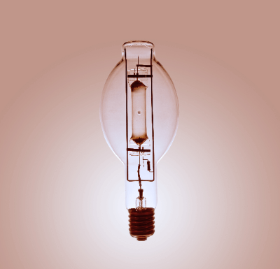
Mercury lamps are lamps that emit blue-white light using mercury vapor. Compared to incandescent lamps, mercury lamps have the advantages of higher luminous efficiency, longer life, and less maintenance.

Mercury lamps are broadly classified into two types based on the mercury vapor pressure at the time of lamp lighting: high-pressure and low-pressure. If the mercury vapor pressure is 10^5 Pa or higher, it is a high-pressure type, and if it is 100 Pa or lower, it is a low-pressure type.

Among high-pressure mercury lamps, there are also ultra-high-pressure types with mercury vapor pressures of 10^6 to several 10^7 Pa.

Uses of Mercury Lamps

Low-pressure mercury lamps are widely used as germicidal lamps because of their property of radiating ultraviolet (UV) light. Low-pressure mercury lamps may also be used as fluorescent lamps by coating the emission tubes with a fluorescent substance, in which case they are used for general lighting and as light sources for UV curing.

Typical applications for high-pressure mercury lamps include general lighting and UV curing. They are also sometimes used for photochemical reaction experiments.

There are two main types of super high-pressure mercury lamps: short-arc type and long-arc type. The former is used for optical microscopes and optical equipment due to its high luminance, while the latter is utilized for plate-making and semiconductor etching.

Principle of Mercury Lamps

Mercury lamps are designed to emit light by filling the light-emitting tube with mercury vapor and discharging the vapor into the mercury vapor.

When a discharge occurs in the light-emitting tube, mercury atoms in a low-energy state collide with electrons, resulting in a high-energy state (excited or ionized state). When the mercury atoms in this high-energy state return to their low-energy state, light equivalent to the difference in energy between the two is emitted.

The light emitted when the mercury ion returns to the mercury atom is called the continuous spectrum. The light emitted when the mercury ion returns from the excited state to the ground state (or metastable state) is called the emission line spectrum.

It is well known that the wavelength of light emitted by mercury lamps varies depending on the vapor pressure of mercury sealed in the light-emitting tube. Specifically, a low mercury vapor pressure strongly emits light with wavelengths in the ultraviolet region, while a high mercury vapor pressure increases light with wavelengths in the visible region.

In other words, low-pressure Mercury Lamps emit more ultraviolet light, making them suitable for sterilization lamp applications.

カテゴリー
category_usa

Adhesive

What Is Adhesive?

Adhesives are tools used to attach substances to substances.

Various types of adhesives vary in terms of the materials to be joined, the temperature at which they are used, and the time required for adhesive strength to develop after bonding. Therefore they should be selected according to the intended use. There are also various conditions under which adhesives cure, such as temperature conditions and the presence or absence of moisture or gas. In addition to the commonly known one-component adhesives, there are also two-component adhesives that can be bonded by mixing the main agent and curing agent.

Uses of Adhesives

A wide range of adhesives is sold, from low-viscosity and smooth ones to high-viscosity and vicious ones. Adhesives with low viscosity can, for example, be post-penetrating, meaning they penetrate through gaps in the threads after the screw has been secured.

Adhesives with high viscosity can be used not only to bond but also to block water and air from entering or leaving the area.

Adhesive Principle

Industrial joining includes screwing, riveting, and welding. Adhesives are used for joining plastic, soft materials, or materials that cannot be tapped by screwing or for joining at an angle. For metal-to-metal joints, welding is sometimes used in addition to adhesive bonding but at a higher cost. Adhesives have recently improved in performance, and a wide variety of adhesives are available for various applications, including those with bonding capabilities as strong as welding and anaerobic adhesives that begin bonding immediately after exposure to air.

Adhesion principles include mechanical bonding, chemical interaction, and physical interaction. Mechanical bonding occurs when the adhesive penetrates the pores and crevices of the material’s surface and cures there. Chemical interactions are formed by chemical reactions in which the adhesive and the object to be bonded share each other’s electrons (i.e. form covalent bonds between atoms). Physical bonding is referred to as intermolecular forces or van der Waals forces and occurs due to the intermolecular attraction that occurs when the adhesive and the object are brought closer together at the atomic level.

カテゴリー
category_usa

Operation Boxes

What Is an Operation Box?

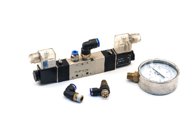
Pneumatic Valves

An operation box, often referred to as a control box, switch box, cabinet box, or enclosure, is designed for housing and organizing control equipment and operating switches. These boxes facilitate the remote control of machines, devices, or equipment from a location separate from the main control panel.

Uses of Operation Boxes

Operation boxes serve a wide range of applications, including:

  • FA control boxes and switch boxes for industrial control equipment.
  • Breakers, control units, and pull boxes for electrical power equipment.
  • Storage boxes for terminal block and equipment in factory settings, facilitating power connections to machine tools.
  • Base stations and outdoor access points for telecommunications equipment.
  • Connection boxes for solar power generation, outdoor measuring instruments, and communication equipment.

These boxes typically accommodate input and display devices such as pushbutton switches, selector switches, indicators, programmable displays, and panel computers.

Principle of Operation Boxes

An operation box includes a main body and a cover that opens via screws or hinges. It mounts control devices for input and display on the cover, allowing operation and visibility even when closed. Inside, a mounting board may be present for attaching additional control devices like control relays and terminal blocks. Cable glands and through holes facilitate the connection of control cables.

Types of Operation Boxes

1. Classification by Structure

Operation boxes vary by their opening mechanism—fixed or retractable—and may include locking features or hand grips for easy adjustment. The size selection depends on the internal components and required cable management.

2. Classification by Material

Materials range from steel, stainless steel, aluminum casting, to polycarbonate and polybutylene terephthalate resins. The choice depends on the application environment, including indoor/outdoor placement and the need for protection against the elements.

3. Protection and Explosion-Proof Types

Operation boxes are classified by dust and waterproof grades (IP Code) and explosion-proof construction for hazardous locations. Selection should match the environmental conditions.

Other Information on Operation Boxes

How to Install an Operation Box

Installation methods include wall-mounted, handheld, and stand types, chosen based on the operation location and user preference.

カテゴリー
category_usa

Microwave Absorbers

What Is a Microwave Absorber?

Radar Absorbing Materials

Radar absorbent material (RAM) is a material that absorbs incident radio waves and suppresses their reflection. It is also called a radio wave-absorbing material. The energy of incident radio waves is converted into heat energy and consumed.

Several types of Microwave Absorbers have different principles of absorbing radio waves depending on the material and shape. The frequency band that can be absorbed differs depending on the type. Therefore, it is necessary to select a Microwave Absorber that matches the application and design it appropriately.

Uses of Microwave Absorbers

The main applications of Microwave Absorbers include noise suppression for electronic devices such as communication equipment and home appliances, anti-reflection for ETC and radar, and evaluation facilities such as anechoic chambers. Microwave Absorbers with characteristics suited to each application are used.

For electronic equipment, a sheet type is used that can shield against specific frequencies emitted by the electronic equipment and can be incorporated into the electronic equipment. On the other hand, for evaluation facilities such as anechoic chambers, Microwave Absorbers in a three-dimensional pyramid shape are used, which have absorption characteristics over a wide frequency band.

Principles of Microwave Absorbers

There are several types of Microwave Absorbers depending on the principle of absorbing radio waves, and the three main types are resistive, inductive, and magnetic.

The resistive type absorbs the energy of radio waves by converting the induced current generated by the incident of radio waves on the conductor into heat energy by consuming it due to the conductor’s own resistance.

The dielectric type uses the resistance component of the carbon particles themselves and the capacitance component between the carbon particles by mixing carbon particles with a dielectric such as foamed polyethylene or rubber. When the incident radio wave is low frequency, almost no electric current is generated. However, as the frequency increases, the impedance of the capacitance component decreases, and an electric current flows. The higher the frequency, the lower the impedance of the capacitive element. The higher the frequency, the more current flows, consumed by the resistor and converted into heat energy to absorb the radio wave energy.

Dielectric types are available in pyramid or sheet forms, depending on their shape. The pyramid type can be designed to absorb a wide range of frequencies because the frequency band to be absorbed is determined not only by the material mixed in but also by its shape.

The magnetic type is made of ferrite or other magnetic materials molded into tile-like shapes, which absorb radio wave energy through magnetic loss. The magnetic type can provide absorption characteristics in the low-frequency band compared to the dielectric type. For this reason, Microwave Absorbers have a wide frequency range by combining dielectric and magnetic types.

Other absorbers have a phase difference of 180 degrees concerning the incident wave to cancel out the reflected wave.

カテゴリー
category_usa

Electricity Meter

What Is a Power Meter?

A power meter is a device used to measure the power consumed by electrical and electronic equipment, also known as loads.

A power meter is inserted between a power source and a load to calculate power from the product of the applied voltage and the flowing current (voltage x current). In AC (alternating current), a phase difference between voltage and current affects the power calculation, making simultaneous measurement essential.

Recently, the quality of the power supply has become a crucial concern, with some meters featuring functions to evaluate the waveforms of voltage, current, and power.

Uses of Power Meters

With the rising importance of reducing energy consumption to address global environmental issues, there’s an increasing need for power meters to monitor the power consumption of various electrical and electronic equipment. Their applications range from electricity saving in households to power monitoring systems in factories and buildings. Highly accurate and sophisticated power meters are also vital for assessing phase angle, power factor, harmonics, flicker, distortion, noise, etc., in development and production environments.

Principle of Power Meters

Electric power, the product of voltage and current, is calculated by measuring these two parameters. For direct current, where both are constant, power calculation is straightforward. However, in alternating current, the phase difference between voltage and current requires continuous measurement of their instantaneous values at the same time.

The power consumed by the load, known as effective power, is the integration and average of the instantaneous power over one cycle. Effective power can be calculated as V × I × cos(θ), where V is the effective voltage, I is the effective current, and θ is the phase difference between voltage and current.

AC power calculations also include reactive power and apparent power, essential for evaluating the efficiency and stability of power supply systems, especially in industrial and utility settings. The power factor, the ratio of active to reactive power, is a key metric for efficiency improvement strategies.

Reactive Power

Generated by the phase difference between current and voltage, reactive power oscillates between the power source and the equipment, influenced by the inductive and capacitive components of the load, and is calculated as V x I x sin(θ).

Apparent Power

Representing the actual flow of current and voltage in a system, apparent power’s equation is the square root of the sum of active power squared and reactive power squared.

How to Select a Power Meter

1. Check the Type of Measurement Target and Required Accuracy

Identify the measurement target (power, current, voltage, power factor, etc.) and the required accuracy, as the measurement range and resolution vary by application.

2. Selecting the Type of Power Meter

Power meters come in analog and digital forms. Analog meters display instantaneous values, while digital meters offer digital displays and data logging capabilities. Choose based on use, environment, and readability.

3. Power Factor and Accuracy Considerations

Evaluate the power factor and accuracy of the power meter, selecting products that maintain a high power factor.

4. Check Communication and Data Collection Capabilities

Modern power meters often feature communication interfaces (like Modbus or Ethernet) and data acquisition capabilities, essential for real-time data collection or remote monitoring.

カテゴリー
category_usa

Trimmer Potentiometers

What Is a Trimmer Potentiometer?

Trimmer Potentiometers

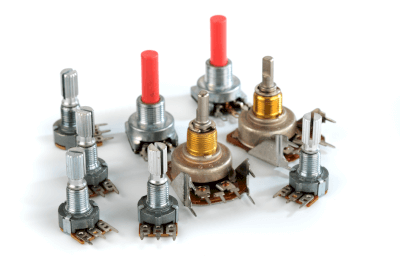
A trimmer potentiometer is a variable resistor whose resistance value can be changed.

They are also called trimmer resistors or trim potentiometers because of their role in adjusting (trimming) the resistance value of a circuit in an electronic device. They adjust for variations due to individual differences in other electronic components.

The resistance of a trimmer potentiometer is adjusted by turning a knob with a driver. There are two types: top-turned and side-turned, and single-turn and multi-turn knobs.

Applications of Trimmer Potentiometers

Trimmer potentiometers are used in a variety of products, including communications equipment, measuring instruments, medical equipment, audiovisual equipment, office equipment, and general electronic equipment. They are applied in situations such as post-production timing adjustment, temperature adjustment, and display brightness adjustment.

Typically, once set, they operate as fixed resistors without being seen by the end user, but they may need to be readjusted during maintenance.

Trimmer potentiometers are often used in hobbyist electronics work, as they are useful for fine-tuning circuit boards.

Principle of Trimmer Potentiometers

The principle of the trimmer potentiometer is simple. When voltage is applied to both terminals (terminals 1 and 3) of a resistive element, the physical position of the contacts (slider or wiper) that move on the resistive element changes the resistance between terminals 2 and 1 (or 3), which is connected to the slider.

A trimmer potentiometer has two roles. Voltage adjustment, in which a larger voltage is lowered to obtain the required voltage. And current adjustment, in which the resistance value is adjusted to change the current value.

When used for voltage adjustment, a trimmer potentiometer is used as a 3-terminal element: voltage is applied between terminals 1 and 3, and the voltage divided by the voltage is taken from terminal 2.

When used for current regulation, a trimmer potentiometer is used as a 2-terminal element, and voltage is applied between terminals 1 and 2 to regulate the current. However, it is safe to leave the unused No. 3 terminal open and connect it to the No. 2 terminal.

The resistance between the two ends of a trimmer potentiometer and the total resistance vary. If the total resistance value is small, the variable range becomes narrower. On the other hand, if the total resistance value is large, the variable range becomes large. However, the setting accuracy becomes lax. Generally, a trimmer potentiometer is selected so that adjustment can be made over a variable range of half the total resistance.

カテゴリー
category_usa

Emergency Stop Switch

What Is an Emergency Stop Switch?

Emergency Stop Switches

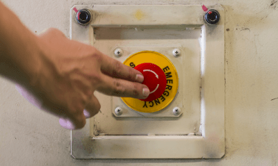
An emergency stop switch is a critical safety device designed to halt equipment operations in emergencies, protecting against serious accidents and injuries. These switches are essential in environments where industrial machinery operates under high torque or pressure, posing risks to human safety.

Uses of Emergency Stop Switches

These switches are commonly found in machinery such as conveyors, presses, and welding robots, where there’s a risk of entrapment or pinching. Regulations often mandate their installation on equipment like conveyor belts to prevent entrapment accidents. Pull-rope switches are preferred in some cases for their accessibility along the length of a conveyor.

Principle of Emergency Stop Switches

  • Push-Button Type: Typically red for visibility, these switches lock when pressed to ensure machinery remains halted until manually reset. They’re designed to interrupt electrical circuits to stop equipment immediately.
  • Pull-Rope Type: Used around conveyors, pulling a wire attached to the switch stops the machine. Like push-button types, these switches lock upon activation and require manual resetting.

Other Information on Emergency Stop Switches

  • Installation Considerations: The placement of emergency stop switches is crucial for easy access by workers. In large facilities, multiple switches are installed to ensure availability in any emergency.
  • Lockout Mechanism: To prevent accidental restarts that could lead to injury or death, some emergency stop switches feature a lockout mechanism. This allows the switch to be padlocked, ensuring that equipment cannot be restarted until it’s safe to do so.
カテゴリー
category_usa

Indicators

What Is an Indicator?

Indicators

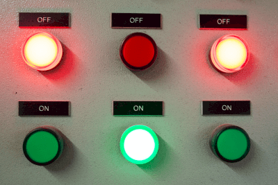
Indicators display the status of devices and other equipment using light. Generally, the term “indicator light” refers to electric indicators.

The history of indicators in the pure sense is long. Lighthouses are the oldest indicators in the sense that they were used to indicate navigation routes. They were in use as early as BC. Modern electric indicators began to be used in the 20th century and have become an indispensable part of daily life and industry.

The mechanism of indicator lamps has changed over time, from flames made from burning combustible materials to gas lamps, etc. Today, most indicator lamps are electric.

Usage of Indicators

The most typical indicators that everyone has seen are probably traffic signals. These lights are used to indicate that traffic is allowed to pass in green, proceed with caution in yellow, and not allowed to pass in red. Another familiar example is the rotating indicators on fire trucks and police cars. 

Rotating indicator lamps and operating status indicator lamps are also used in production sites in a wide range of applications.

Principle of Indicators

The principle of operation of indicator lamps has changed from the past to the present.

In the past, indicator lamps were made of bean bulbs. A miniature light bulb is a glass shell containing a light-emitting filament and an inert gas. When an electric current flows through the luminous filament, it produces heat and light at the same time. The bean bulb is covered with colored glass or resin to display a specific color. Bean bulbs have the disadvantage that if the inert gas inside is removed, the filament burns out or otherwise malfunctions. In the rotating indicator light, a motor for rotation is used at the same time as the bean bulb. The motor rotates the reflector so that it circles the light bulb to attract attention. While rotating indicators are more conspicuous than ordinary indicators, they have the disadvantage of requiring more parts due to the built-in motor.

Currently, LED indicators are the mainstream choice, as LEDs are diodes that emit light when voltage is applied, and unlike filaments, they generate little heat, resulting in long life and high efficiency. In recent years, LED indicators that blink repeatedly have been sold in place of rotating lights.

カテゴリー
category_usa

Wireless Modems

What Is a Wireless Modem?

A modem is a word coined from the initial letters of modulator and demodulator and generally refers to a device that mutually converts analog signals on coaxial cables or telephone lines into digital signals for computers and smartphones.

A wireless modem is a device that uses wireless communication as the transmission path for the modem’s line, instead of wired lines such as optical or telephone lines.

Wireless modems have become popular in recent years because people who move frequently do not need to re-contract their Internet connection with each move.

Uses of Wireless Modems

Business people often use wireless modems to connect to their computers and access the Internet on business trips or at home. Among the most popular general-purpose wireless modems are recent small USB-type modems that can be connected to a PC and then used to wirelessly connect to broadband Internet with a base station.

Currently, Wi-Fi communication is the most common, as well as 4G (LTE), 5G, and other mobile terminal communication standards.

Principle of Wireless Modem

The operating principles of modulation and demodulation, which are the main roles of a modem, are explained below:
Modulation refers to the conversion of a digital signal into an analog signal. Specifically, this is the operation of putting digital information onto an analog signal by placing signal amplitude and phase information on a carrier wave (carrier).
Demodulation, conversely, is the process of extracting the desired digital information from the carrier.

The types of wireless communication used for carriers include 3G (WCDMA) and 4G (LTE), which are the communication standards for mobile terminals, and 5G, which is now becoming the mainstream communication standard.

Wi-Fi operates on carrier frequencies in the 2.4GHz and 5GHz bands, which are the main communication standards for wireless LAN. Although the 5GHz band offers the most stable communication, it is usually shared with the 2.4GHz band (which can fly farther due to its shorter range and susceptibility to obstacles).

There are also packet communications, specific amateur radio communications, and other low-power radios such as the ISM band (2.4GHz).